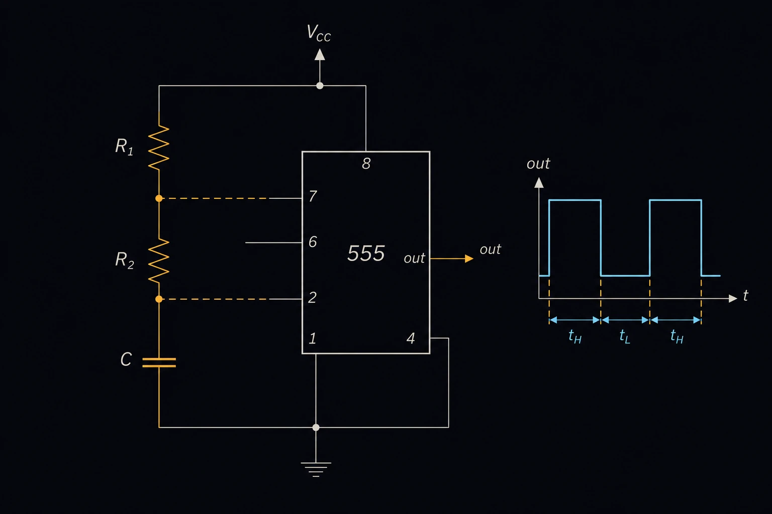
555 Timer (Astable Mode)
Designs the classic 555 timer astable (free-running) oscillator. Enter R1, R2 and the timing capacitor C to get the output frequency, period and duty cycle. Or enter a target frequency and solve for the capacitor or for R2, with the nearest standard part from an E-series [2]. Hobbyists and circuit designers use it for LED flashers, clock pulses, tone generators and simple PWM sources.
Equations
f = 1.44 / ((R1 + 2R2)·C) D = (R1 + R2) / (R1 + 2R2) T = 1/f
The capacitor charges through R1 and R2 from one third to two thirds of the supply voltage while the output is high. It then discharges through R2 alone while the output is low [1]. Each half takes 0.693 time constants (ln 2), so the high time is 0.693(R1 + R2)C and the low time is 0.693R2C. Adding them gives the period T, and 1.44 is 1/0.693 rounded. f is the frequency in hertz, and D is the duty cycle, the fraction of each period that the output is high. Because the supply voltage cancels out, it does not appear in the result.
Limits and common mistakes
- The duty cycle is always above 50 %, because the capacitor charges through both resistors but discharges through R2 only. Getting 50 % or less needs a diode across R2, which this page does not model.
- R1 must not be zero in a real circuit. It limits the current into the discharge pin when that pin turns on [1].
- The equations ignore the IC’s own delays and the capacitor’s tolerance. Electrolytic capacitors are often ±20 % and leak, so the real frequency can be well off. Use film or ceramic capacitors where accuracy matters.
- The nearest standard value changes the frequency slightly. Recalculate with the part you choose.
Worked example
A warning beacon needs an LED that flashes once per second. R1 is 10 kΩ and R2 is 68 kΩ, both from stock. What capacitor is needed?
- Choose Solve for Timing Capacitor (C) (given target Frequency, R1 & R2).
- Enter R1 10 kΩ and R2 68 kΩ.
- Enter Target Frequency (f) 1 Hz.
- Choose Also show the nearest standard capacitor from (IEC 60063) E12 (±10 %) and press Solve. The Solution shows:
Required Capacitor (C): 9,863.01 nF
Nearest E12 value (±10 %): 10 µF (1.4 % above)
Duty cycle: 53.4247 %
Period (T): 1 s
Check by hand: R1 + 2R2 = 146 kΩ, and 1.44 / 146,000 = 9.863 µF. The duty cycle is 78/146 = 53.4 %. With the 10 µF part fitted, the frequency becomes 1.44 / (146,000 × 10 × 10−6) = 0.986 Hz, close enough for a beacon.