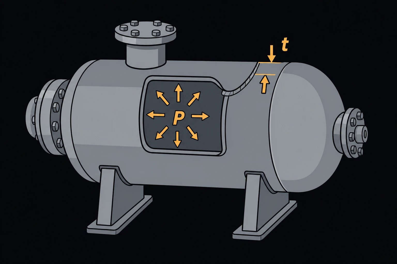
Pressure Vessel Wall Thickness (ASME VIII-1)
Finds the wall thickness that internal pressure needs in a cylindrical shell, a 2:1 ellipsoidal head or a hemispherical head, by the rules of ASME Section VIII, Division 1 [1]. It looks up the allowable stress and weld joint efficiency, then adds the corrosion allowance. Use it to size vessels and drums, and to check a vendor’s figures.
Equations
Shell (UG-27): t = P·R/(S·E − 0.6P)
2:1 ellipsoidal head (UG-32): t = P·D/(2S·E − 0.2P)
Hemispherical head (UG-32): t = P·R/(2S·E − 0.2P)
t is the pressure-design thickness, before corrosion allowance. P is the internal design pressure (gauge), D the inside diameter and R = D/2 the inside radius. S is the maximum allowable stress of the material at the design temperature [3]. E is the joint efficiency of the weld seam, from Table UW-12 [1]. The shell formula is for the circumferential (hoop) stress, which governs over the longitudinal stress [2].
Inputs
- Choosing a Material fills in S from Table 1A of Section II, Part D at −20 to 100 °F [3]. Above 100 °F, S falls; look it up for your design temperature and type it in.
- Weld Joint and Radiographic Examination set E. For a double-welded butt joint: full radiography 1.0, spot 0.85, none 0.70 [1].
- MAWP at thickness t puts t back into the formula, so it returns the design pressure. It is a check on the arithmetic, not the rating of a real plate.
Limits and common mistakes
- The formulas hold for thin walls: t up to R/2 and P up to 0.385 S·E for a shell [1]. Beyond that, use Appendix 1.
- The page uses the uncorroded radius and adds the allowance afterwards. The code uses the corroded radius, R + CA, which gives a slightly thicker wall.
- The result is a minimum. Round up to a stock plate, and allow for mill under-tolerance and thinning when a head is formed.
- This is internal pressure only. Vacuum, wind, nozzle loads and static head need their own checks.
Worked example
A carbon steel separator, 1200 mm inside diameter, is designed for 2000 kPa gauge at ambient temperature. The shell is SA-516 Gr. 70 plate with double-welded butt seams and spot radiography, with a 3 mm corrosion allowance. How thick must the shell be?
- Choose Component Cylindrical shell (circumferential stress).
- Enter Internal Design Pressure 2000 kPa and Inside Diameter 1200 mm.
- Choose Material SA-516 Gr. 70 plate (20.0 ksi). S fills in as 137.895145863 MPa, which is 20 ksi exactly.
- Choose Weld Joint Type 1 — double-welded butt and Radiographic Examination Spot RT.
- Enter Corrosion Allowance 3 mm and press Solve. The Solution shows:
Equation: t = PR/(SE − 0.6P)
Joint efficiency E: 0.85
Joint efficiency basis: ASME VIII-1 Table UW-12 — Type 1, spot radiography
Pressure-design thickness t: 10.3439 mm
t + corrosion allowance: 13.3439 mm
MAWP at thickness t: 2 MPa
Check by hand: S·E = 137.895 × 0.85 = 117.21 MPa, so t = 2 × 600/(117.21 − 1.2) = 10.34 mm. With the corroded radius of 603 mm the code gives 10.40 mm. With the 3 mm allowance, a 14 mm plate covers either.