Beam Deflection
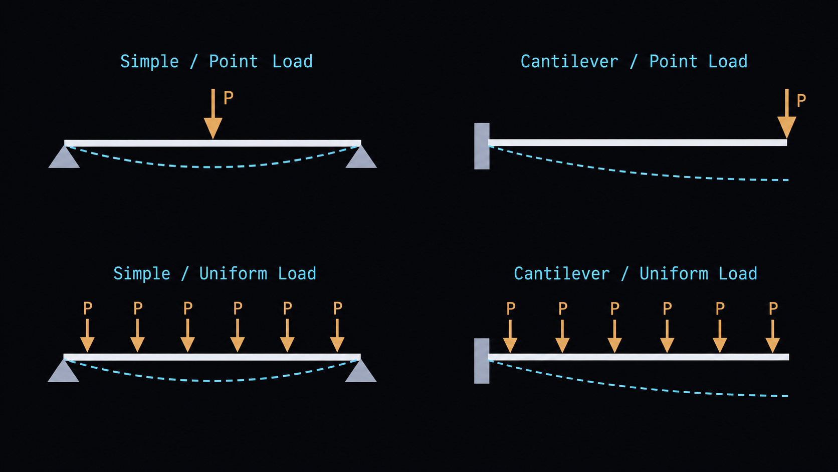
Finds the maximum deflection of a simply supported beam or a cantilever under a point load or a uniform load. It can also work the other way: from a deflection limit, it gives the second moment of area I the beam needs. Pick a metal or lumber species for E and an AISC shape for I, or type your own. Designers use it to size joists, beams and brackets for stiffness.
Equations
Simple, point load at midspan: δ = P·L3/(48·E·I) Cantilever, point load at the free end: δ = P·L3/(3·E·I)
Simple, uniform load: δ = 5·w·L4/(384·E·I) Cantilever, uniform load: δ = w·L4/(8·E·I)
P is the point load, w the uniform load per unit length, L the span (or the cantilever’s length), E the elastic modulus and I the second moment of area about the bending axis [1]. δ is at midspan for a simple beam and at the free end for a cantilever. A listed shape fills in Ix, for bending about its strong axis [2]. A lumber species fills in its reference E [3]. To find I, the same equations are solved for I with δ set to the limit. A code limit from IBC Table 1604.3 [4] or ACI 318 Table 24.2.2 [5] allows span/n. For a cantilever, both codes take the span as twice its length.
Limits and common mistakes
- The equations are for small, elastic deflections of a straight, prismatic beam. Shear deflection is ignored.
- The point load is at midspan for a simple beam. A load off center deflects the beam less.
- Use the load the limit applies to: live load alone for L/360, dead plus live for L/240.
- The page doesn’t check strength.
- A channel bends as listed only if the load passes through its shear center or it is braced. The page says so when you pick one.
Worked example
A steel floor beam spans 6 m between supports and carries a live load of 15 kN/m (15 N/mm). The floor must meet the IBC live-load limit of L/360.
- Choose Beam Case Simple / Uniform Load and Solve for Second Moment of Area (I).
- Enter Uniform Load (w) 15 N/mm and Span Length (L) 6000 mm. Choose Material (E) Steel.
- Choose Deflection Limit Live load — L/360 under Floor members, and press Solve. The Solution shows:
Second Moment of Area (I): 75,937,500 mm⁴
Allowable deflection δ = L/360: 16.6667 mm - That is 182 in⁴. To check a W12x26 (Ix = 204 in⁴), choose Solve for Deflection (δ), Section Type W-Shape and Section W12x26, and press Solve: Maximum Deflection (δ): 14.9053 mm
Check by hand. Ix = 204 × 25.44 = 84.9 × 106 mm⁴, and 5 × 15 × 60004 / (384 × 200,000 × 84.9 × 106) = 14.9 mm. That is under the 16.7 mm limit, as it must be with more than the 182 in⁴ required.