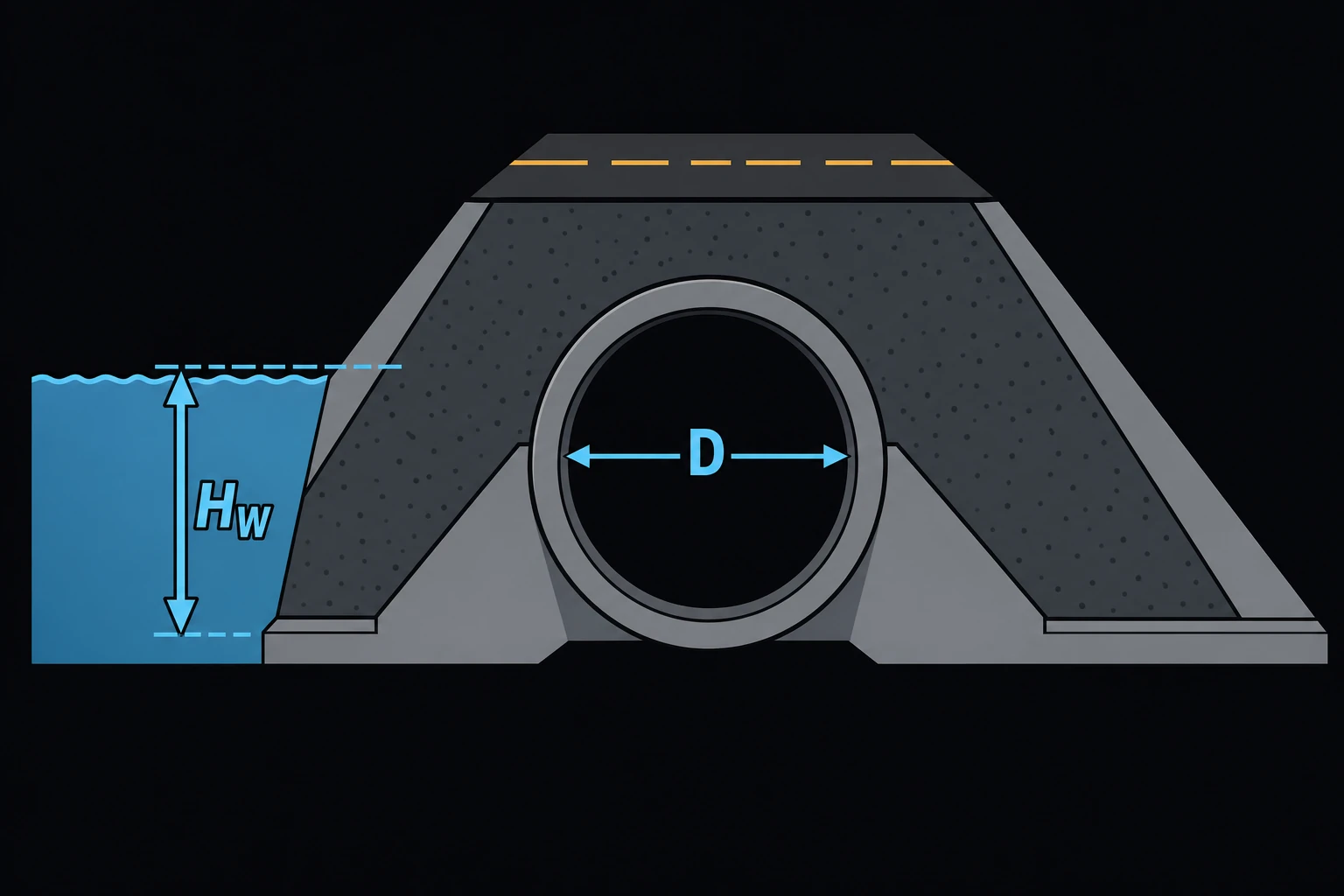
Culvert Capacity — Inlet Control (Approximate)
Finds how deep water ponds at a culvert inlet for a given flow, or how much flow a culvert passes at a given headwater, when the inlet controls. It covers circular concrete and corrugated metal pipes and concrete box culverts, using the FHWA HDS-5 equations [1]. Highway and site designers use it for a first sizing of a culvert under a road or embankment.
Equations
When the inlet is not submerged (Q/AD0.5 ≤ 3.5), it acts like a weir:
HW/D = Hc/D + K·(Ku·Q/(A·D0.5))M + Ks·S
When it is submerged (Q/AD0.5 ≥ 4.0), it acts like an orifice:
HW/D = c·(Ku·Q/(A·D0.5))2 + Y + Ks·S
HW is the headwater depth above the inlet invert, D the diameter or box rise, A the barrel area, Q the discharge and S the barrel slope. Hc is the specific head at critical depth, dc + Vc²/2g. K, M, c and Y depend on the inlet type (HDS-5 Table A.1), and Ks is −0.5, or +0.7 for a mitered inlet. The constants were fitted in US units, so Ku = 1.811 converts the SI group to ft0.5/s. Between 3.5 and 4.0 the page interpolates between the two curves, so the headwater rises smoothly with flow. The Standard Size list gives ASTM C76 concrete pipe diameters [2].
Limits and common mistakes
- This is inlet control only. A culvert passes the smaller of its inlet-control and outlet-control capacities. A long, rough or flat barrel, or high tailwater, often puts it in outlet control, which this page does not check. Use HDS-5 or HY-8 for the final design.
- HW is measured from the inlet invert, not from the channel bed or the outlet.
- Pick the inlet that will be built. A projecting corrugated pipe needs far more headwater than a groove-end concrete pipe in a headwall.
- Very small flows at steep slopes can drive the equations to a headwater at or below the invert. The page reports an error instead of a value.
Worked example
A 36 in (914.4 mm) reinforced concrete pipe with a groove end in a headwall must carry the 2 m³/s design flow under a farm road. The barrel slopes at 1 %. How high will the water rise at the inlet?
- Choose Solve For Headwater from discharge, Culvert Shape Circular and Inlet Type (circular) Concrete pipe — groove end with headwall.
- Choose Standard Size 36 in. (914.4 mm).
- Enter Discharge (Q) 2 m³/s and Barrel Slope (S) 0.01 and press Solve. The Solution shows:
Inlet-control headwater HW: 1.56068 m
HW / D: 1.70678
Discharge intensity Q/AD^0.5 (US units): 5.76889 ft^0.5/s
Flow regime: Submerged inlet — HDS-5 orifice equation
Barrel area A: 0.656693 m²
Check in US units. 2 m³/s is 70.63 ft³/s and the pipe is 3 ft across, so A = 7.069 ft² and Q/AD0.5 = 70.63/(7.069 × 1.732) = 5.77. That is above 4.0, so the orifice equation applies: HW/D = 0.0292 × 5.77² + 0.74 − 0.005 = 1.707, and HW = 5.12 ft = 1.561 m. The road surface must sit well above 1.56 m over the inlet invert, and outlet control still needs checking.