Filter Design
Works out the corner frequency of a first-order RC low-pass or high-pass filter, or the capacitor needed for a target corner, with the nearest standard value. For a band-pass made of a high-pass stage followed by a low-pass stage, it gives the true −3 dB band, center frequency, Q and peak gain. Use it for anti-alias filters, audio tone shaping, sensor smoothing and coupling networks.
Equations
fc = 1/(2πRC) C = 1/(2πR·fc)
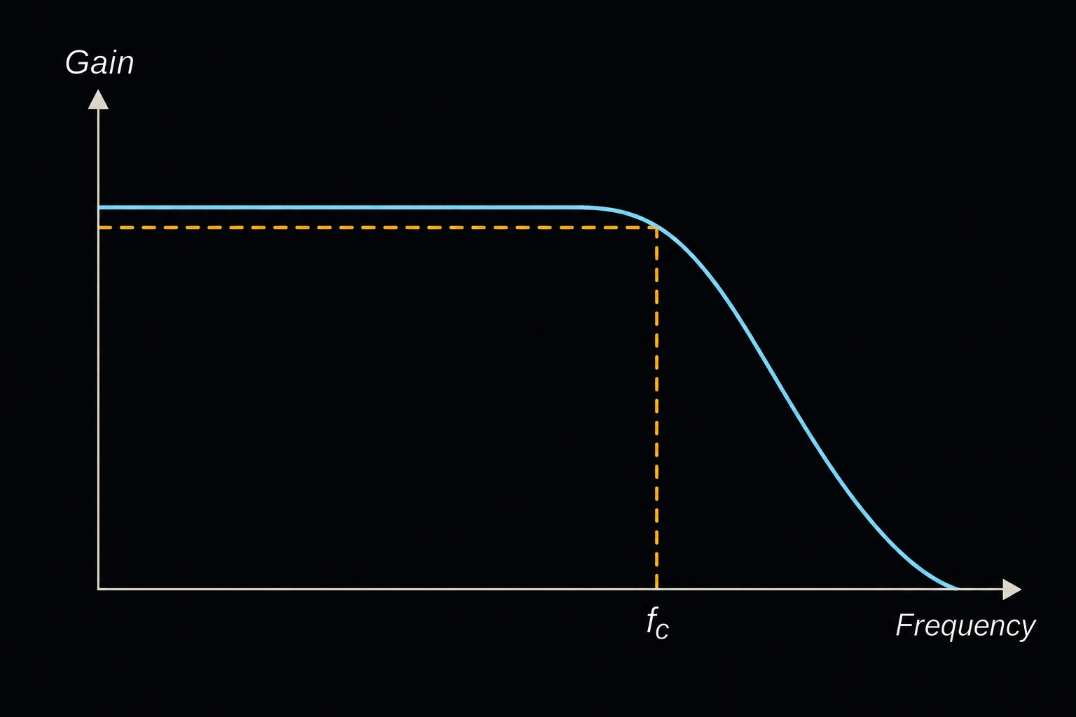
R is the resistance, C the capacitance and fc the cutoff (corner) frequency in hertz. At fc the output is 3 dB down, about 70.7 % of the input, and beyond it the response rolls off at 20 dB per decade [1]. The same formula holds for the low-pass (R in series, C to ground) and the high-pass (C in series, R to ground). When solving for C, the page also gives the nearest value in the chosen IEC 60063 series [2].
fL = 1/(2πR1C1) fH = 1/(2πR2C2)
f0 = √(fL·fH) Q = f0/(fL + fH)
For the band-pass, fL and fH are the corners of the high-pass and low-pass stages on their own. f0 is the center frequency, where the gain peaks. Together the stages form one second-order filter [1]. Its −3 dB edges are f0·(√(1 + 1/4Q2) ∓ 1/2Q), so the bandwidth is fL + fH. The peak gain is 20·log10(fH/(fL + fH)) dB, a little below 0 dB.
Limits and common mistakes
- The band-pass edges are not fL and fH. The stages overlap, so the real band is wider, and Q can never exceed 0.5. For a narrow, sharp band use an active second-order filter.
- The results assume the source has low impedance and the load high impedance. In the band-pass, buffer the stages (for example with an op-amp follower) or the second stage loads the first and both corners shift.
- A first-order filter only cuts 20 dB per decade. A signal at twice fc is reduced by only about 7 dB.
- Ceramic capacitors can lose much of their value with DC bias and temperature. Use C0G/NP0 or film parts where the corner matters.
Worked example
A voice channel needs roughly 300 Hz to 3.4 kHz. The parts on hand give a buffered high-pass stage of 10 kΩ and 47 nF and a low-pass stage of 4.7 kΩ and 10 nF. What band does it really pass?
- Choose Filter Type Band-pass (two-stage RC).
- Enter High-pass stage R1 (sets low cutoff) 10 kΩ and High-pass stage C1 47 nF.
- Enter Low-pass stage R2 (sets high cutoff) 4.7 kΩ and Low-pass stage C2 10 nF, and press Solve. The Solution shows:
Lower −3 dB frequency: 285.899 Hz
Upper −3 dB frequency: 4,010.8 Hz
Center frequency (f0): 1,070.83 Hz
Bandwidth (BW): 3,724.9 Hz
Quality factor (Q): 0.28748
Peak gain at f0: -0.827854 dB
High-pass stage corner 1/(2πR1C1): 338.628 Hz
Low-pass stage corner 1/(2πR2C2): 3,386.28 Hz
Check by hand: 1/(2π×10 kΩ×47 nF) = 338.6 Hz and 1/(2π×4.7 kΩ×10 nF) = 3386 Hz. Their sum, 3725 Hz, is the bandwidth, and √(338.6 × 3386) = 1071 Hz is the center. The real band, 286 Hz to 4.01 kHz, is wider than the two corners suggest, as expected for overlapping stages.