Gear Design
Finds the basic geometry of a pair of standard spur gears: pitch, base and outside diameters, center distance, ratio and contact ratio. It also warns when the teeth interfere or the contact ratio is too low to run smoothly. Choose a standard module or diametral pitch, the two tooth counts and the pressure angle. Designers use it to lay out a gear pair before checking tooth strength and ordering gears.
Equations
d = m·N a = (d1 + d2)/2 db = d·cos φ da = d + 2m
mc = [√(ra1² − rb1²) + √(ra2² − rb2²) − a·sin φ] / (π·m·cos φ)
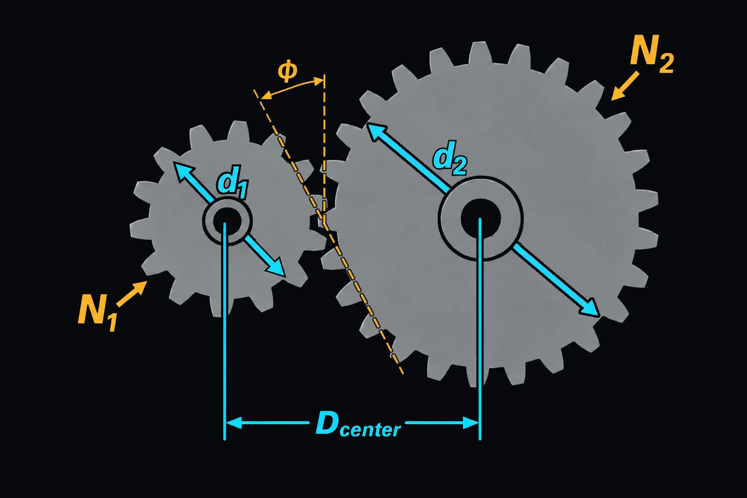
m is the module, the pitch diameter per tooth in mm. A diametral pitch P (teeth per inch of pitch diameter) is converted with m = 25.4/P. N1 and N2 are the pinion and gear tooth counts, d the pitch diameter, a the center distance, φ the pressure angle, db the base diameter the involute is generated from, and da the outside (tip) diameter. ra and rb are the tip and base radii. Full-depth teeth have an addendum of one module [1], [3]. The contact ratio mc is the length of the path of contact divided by the base pitch: the average number of tooth pairs in mesh [1]. The gear ratio is N2/N1.
The page flags interference when either tip circle reaches past the point where the line of action touches the other gear’s base circle [1]. The modules are the ISO 54 series [2]; the diametral pitches are those in general use [1].
Limits and common mistakes
- The page covers standard, full-depth spur gears without profile shift. Helical gears, stub teeth and shifted profiles have other diameters and center distances.
- It gives geometry only, not tooth strength or wear. Check bending and contact stress before choosing a face width.
- With 20° teeth a pinion of fewer than about 18 teeth can interfere with a large gear. Use more teeth or a 25° pressure angle rather than undercut teeth.
- Keep the contact ratio at 1.2 or more for smooth, quiet running.
Worked example
A conveyor drive needs a 2.5:1 speed reduction with spur gears of module 2.5. Try an 18-tooth pinion on a 45-tooth gear and find the center distance for the gearbox housing.
- Choose Tooth Size m = 2.5 mm. The module fills in as 2.5 mm.
- Enter Pinion Teeth 18 and Gear Teeth 45.
- Choose Pressure Angle 20° and press Solve. The Solution shows:
Pinion Pitch Diameter (d1): 45 mm
Gear Pitch Diameter (d2): 112.5 mm
Center Distance: 78.75 mm
Gear Ratio (N2/N1): 2.5
Pinion Base Diameter (db1 = d1·cos φ): 42.2862 mm
Gear Base Diameter (db2 = d2·cos φ): 105.715 mm
Pinion Outside Diameter (d1 + 2m): 50 mm
Gear Outside Diameter (d2 + 2m): 117.5 mm
Contact Ratio (mc): 1.63281
Check: the center distance is m·(N1 + N2)/2 = 2.5 × 63/2 = 78.75 mm. No note appears, so the teeth don’t interfere, and a contact ratio of 1.63 is typical of 20° spur gears.