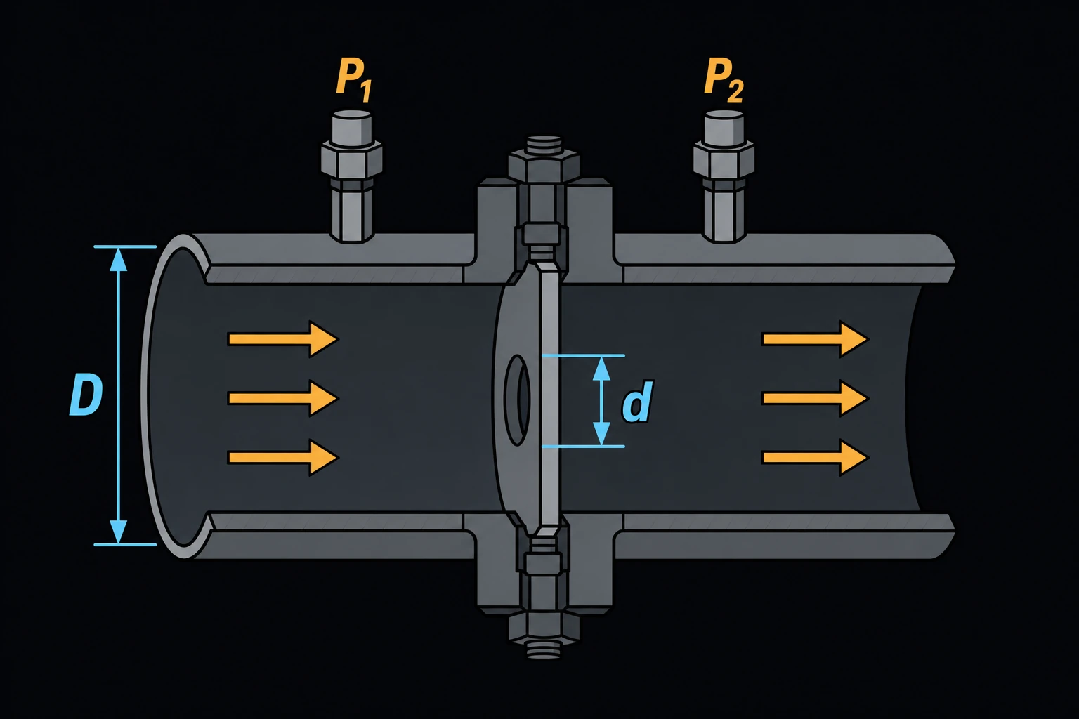
Orifice Plate Flow (ISO 5167)
Turns the differential pressure across an orifice plate into a mass and volumetric flow rate, using the ISO 5167-2 flow equation [1]. Instrument and process engineers use it to check a flowmeter reading, to set a transmitter range or to see what flow a given plate gives.
How the flow is calculated
qm = C·E·ε·(π/4)·d2·√(2·ΔP·ρ1)
where qm is the mass flow, C the discharge coefficient, d the bore diameter of the plate, ΔP the differential pressure between the taps and ρ1 the fluid density at the upstream tap. The velocity of approach factor E = 1/√(1 − β4) corrects for the flow already moving in the pipe, with β = d/D and D the pipe inside diameter. The expansibility factor ε corrects for a gas expanding through the bore; it is 1.0 for a liquid. The volumetric flow is qv = qm/ρ1, at upstream conditions.
The page does not work out C or ε for you. Take C from the plate’s sizing sheet, or from the Reader–Harris/Gallagher equation in ISO 5167-2 [1, 2]; it depends on β, the Reynolds number and the tap positions, and is near 0.60 for most plates. For a gas, ISO 5167-2 gives ε = 1 − (0.351 + 0.256β4 + 0.93β8)·[1 − (p2/p1)1/κ], with p2/p1 the downstream-to-upstream pressure ratio and κ the isentropic exponent. Picking a pipe size fills D from ASME B36.10M [3], and picking a fluid fills its density [4–7].
Limits and common mistakes
- ISO 5167-2 covers D from 50 to 1000 mm, d of at least 12.5 mm, β from 0.10 to 0.75 and a pipe Reynolds number of at least 5000. Outside that, C is not known to the standard’s uncertainty.
- Use the measured inside diameter of the pipe, not its nominal size.
- ΔP is the reading between the taps, not the permanent pressure loss, which is smaller.
- ρ1 is the density at the upstream tap. For a gas, use the flowing pressure and temperature, not standard conditions.
- The plate needs enough straight pipe upstream. Bends and valves close to it shift C.
Worked example
A 4 in. Schedule 40 cooling-water line has an orifice plate with a 60 mm bore and flange taps. The transmitter reads 25 kPa. The water is at 20 °C, and the sizing sheet gives C = 0.609. What is the flow?
- Choose Pipe Size NPS 4 and Schedule Sch 40.
- Enter Orifice Bore Diameter 60 mm and Differential Pressure 25 kPa.
- Choose Fluid Water, 20°C, and enter Discharge Coefficient 0.609 and Expansibility Factor 1.
- Press Solve. The Solution shows:
Diameter ratio β = d/D: 0.58674
Velocity of approach factor E: 1.06511
Mass flow qm: 12.9568 kg/s
Mass flow qm: 46,644.4 kg/h
Volumetric flow qv: 46.7285 m³/h
Check by hand. β = 60/102.26 = 0.5867 and the bore area is 2.827×10⁻³ m². √(2 × 25,000 × 998.2) = 7,065, so qm = 0.609 × 1.0651 × 2.827×10−3 × 7,065 ≈ 12.96 kg/s. The Reynolds number is about 161,000, and the Reader–Harris/Gallagher equation for flange taps gives C ≈ 0.609 there, so the coefficient fits. Flow goes as √ΔP: a reading of 100 kPa would double it.