RC/RL/RLC Time Constant
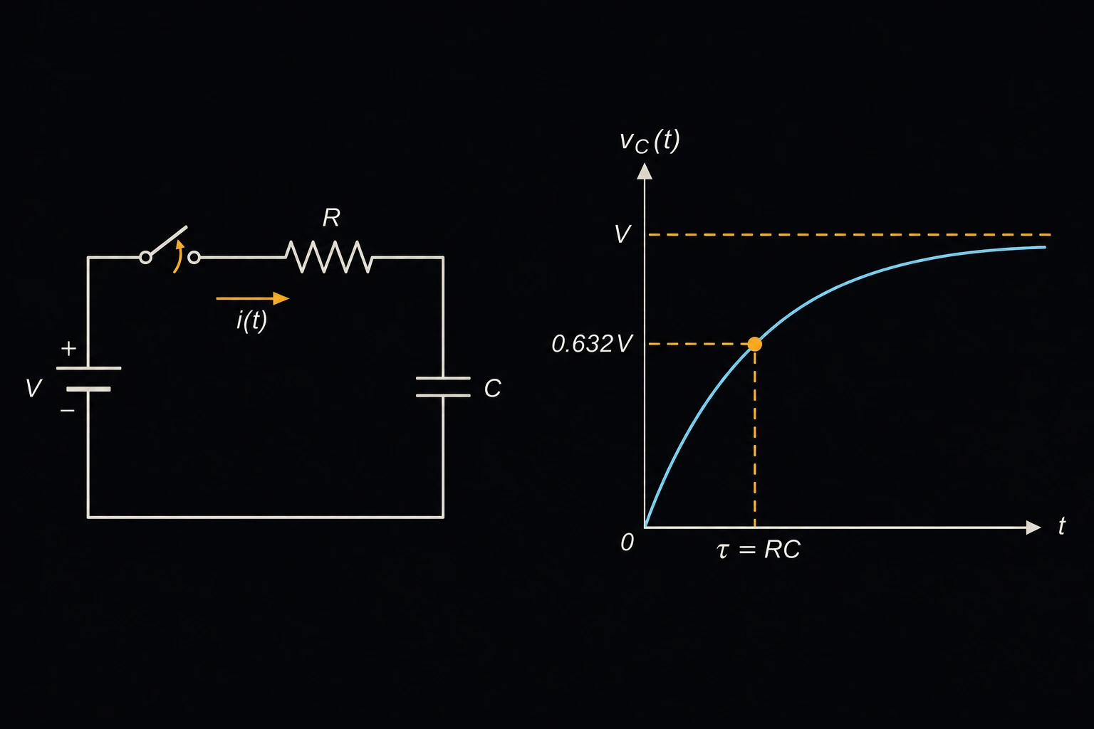
Finds how fast a simple circuit responds after a switch closes. For an RC or RL circuit it gives the time constant and the time to reach any percentage of the full change. For a series RLC circuit it gives the natural frequency, the damping ratio and whether the circuit rings. Designers use it to set reset and debounce delays, filter settling times and snubber values. The live curve below the Solution plots the response and reads it at any time you pick.
Equations
τ = R·C τ = L/R t = τ·ln(1/(1 − p/100))
τ is the time constant in seconds, R the resistance, C the capacitance and L the inductance [1]. After a step, the capacitor voltage of an RC circuit or the inductor current of an RL circuit covers the fraction 1 − e−t/τ of its total change. t is the time to cover p percent of it. One time constant gives 63.2 %, three give 95.0 % and five give 99.3 %. A discharge follows the same curve downward, so 70 % of the way down takes the same time as 70 % of the way up.
ω0 = 1/√(L·C) ζ = (R/2L)/ω0 ωd = ω0·√(1 − ζ²)
For a series RLC circuit, ω0 is the undamped natural frequency, R/2L the decay rate and ζ the damping ratio [1]. Below ζ = 1 the circuit is underdamped and rings at the damped frequency ωd. At ζ = 1 it is critically damped, the fastest response with no overshoot. Above 1 it is overdamped and creeps to its final value. All three frequencies are in rad/s; divide by 2π for hertz.
Limits and common mistakes
- R is the total resistance in the loop: the resistor plus the source’s output resistance, the winding resistance of the inductor and any switch resistance.
- Capacitor tolerance is often ±10 % to ±20 %, and electrolytic types lose capacitance with age and cold. Leave margin on any delay that matters.
- The equations assume ideal, linear parts and a clean step. A load that draws current from the capacitor, or an inductor core that saturates, changes the curve.
- The RLC result is the natural (source-free) response of a series circuit. A parallel RLC circuit has a different damping ratio.
Worked example
A power-on reset holds a controller off until its enable pin passes 70 % of the supply voltage. The pin is fed through 47 kΩ and has a 10 µF capacitor to ground. How long is the delay?
- Choose Circuit RC (resistor-capacitor).
- Enter Resistance (R) 47 kΩ and Capacitance (C) 10 µF.
- Enter Target % of full transition 70 and press Solve. The Solution shows:
Time constant (τ): 0.47 s
Time to reach 70%: 0.565867 s
Check: τ = 47,000 Ω × 10×10−6 F = 0.47 s, and ln(1/0.3) = 1.204, so t = 0.566 s. 70 % lies a little past one time constant (63.2 %), so a delay just over τ is what to expect.