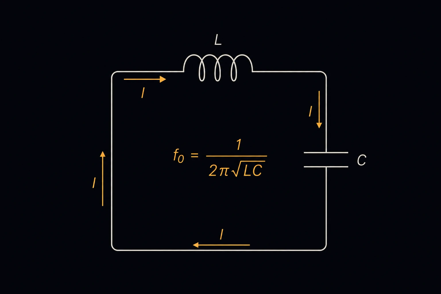
Resonant Frequency (LC Circuits)
Finds the frequency at which an inductor and a capacitor resonate, and the quality factor Q of the circuit they form with a resistance. It can also work the other way: give a target frequency and the page finds the capacitance, along with the nearest standard capacitor value. Use it to tune filters, oscillator tanks, wireless-charging coils and notch traps.
Equations
f0 = 1/(2π√(L·C)) C = 1/((2πf0)²·L)
f0 is the resonant frequency in hertz, L the inductance in henries and C the capacitance in farads [1]. At f0 the reactances of the inductor and the capacitor are equal and cancel. A series circuit then has its lowest impedance, just R. A parallel circuit has its highest. The same formula holds for both when the parts are ideal.
Qseries = ω0·L/R Qparallel = R/(ω0·L)
ω0 = 2πf0 is the angular resonant frequency and R the resistance [1]. In a series circuit, R is the resistance in the loop with L and C, so a smaller R gives a higher Q. In a parallel circuit, R is the resistance across the tank, so a larger R gives a higher Q. Q sets the sharpness of the peak: the bandwidth between the half-power points is about f0/Q. Set R to 0 to skip Q.
The nearest standard value comes from the E-series you pick, as defined in IEC 60063 [2], with how far it lies from the exact capacitance.
Limits and common mistakes
- Don’t mix up the two meanings of R. Putting a coil’s small series resistance into the parallel formula gives a Q that is far too low.
- Real inductors have winding capacitance, and real capacitors have lead inductance. Near a part’s self-resonant frequency the simple formula no longer holds.
- Wiring and board traces add a few picofarads. At radio frequencies, with small capacitors, that shifts f0 noticeably.
- A standard capacitor moves the frequency: f0 scales with 1/√C, so a capacitor 2 % low raises f0 by about 1 %.
Worked example
A series resonant circuit must be tuned to 50 kHz with a 100 µH inductor whose winding resistance is 2 Ω. What capacitor does it need, and how sharp is the peak?
- Choose Circuit Series RLC and Solve for Capacitance (C).
- Enter Inductance (L) 100 µH and Target Resonant Frequency (f0) 50 kHz.
- Enter Resistance (R) 2 Ω, and choose Also show the nearest standard capacitor from (IEC 60063) E12 (±10 %). Press Solve. The Solution shows:
Required Capacitance (C): 0.101321 µF
Nearest E12 value (±10 %): 100 nF (1.3 % below)
Resonant frequency (f0): 50,000 Hz
Quality factor (Q): 15.708
Check: (2π × 50,000)² = 9.87×10¹⁰, and 1/(9.87×1010 × 10−4) = 1.013×10⁻⁷ F, or 0.1013 µF. With the 100 nF part, f0 rises to 50.3 kHz. The bandwidth is about 50,000/15.7 = 3.2 kHz.