Wire/Cable Sizing & Voltage Drop
Checks whether a copper or aluminum building wire can carry a load, and how much voltage it loses on the way. Check a gauge you have chosen, or let the page find the smallest gauge, up to 4/0 AWG, that meets both the ampacity and a voltage-drop limit. Electricians and designers use it to size branch circuits and feeders under the National Electrical Code (NEC) [1].
Ampacity
Iallow = min(Itable·kT·kN, Iterm)
Itable is the ampacity from NEC Table 310.16 for the conductor’s material and insulation temperature rating. kT is the ambient correction factor of Table 310.15(B)(1)(1), and kN the adjustment factor of Table 310.15(C)(1) for more than three current-carrying conductors together [1]. Iterm is the Table 310.16 value in the column of the terminal rating. Under NEC 110.14(C) a 90 °C wire may be derated from its 90 °C value but can’t be used above the terminals’ column [1]. In check mode, 14 to 10 AWG also show the largest breaker or fuse NEC 240.4(D) allows for them.
Voltage drop
Vd = 2·K·I·L / A
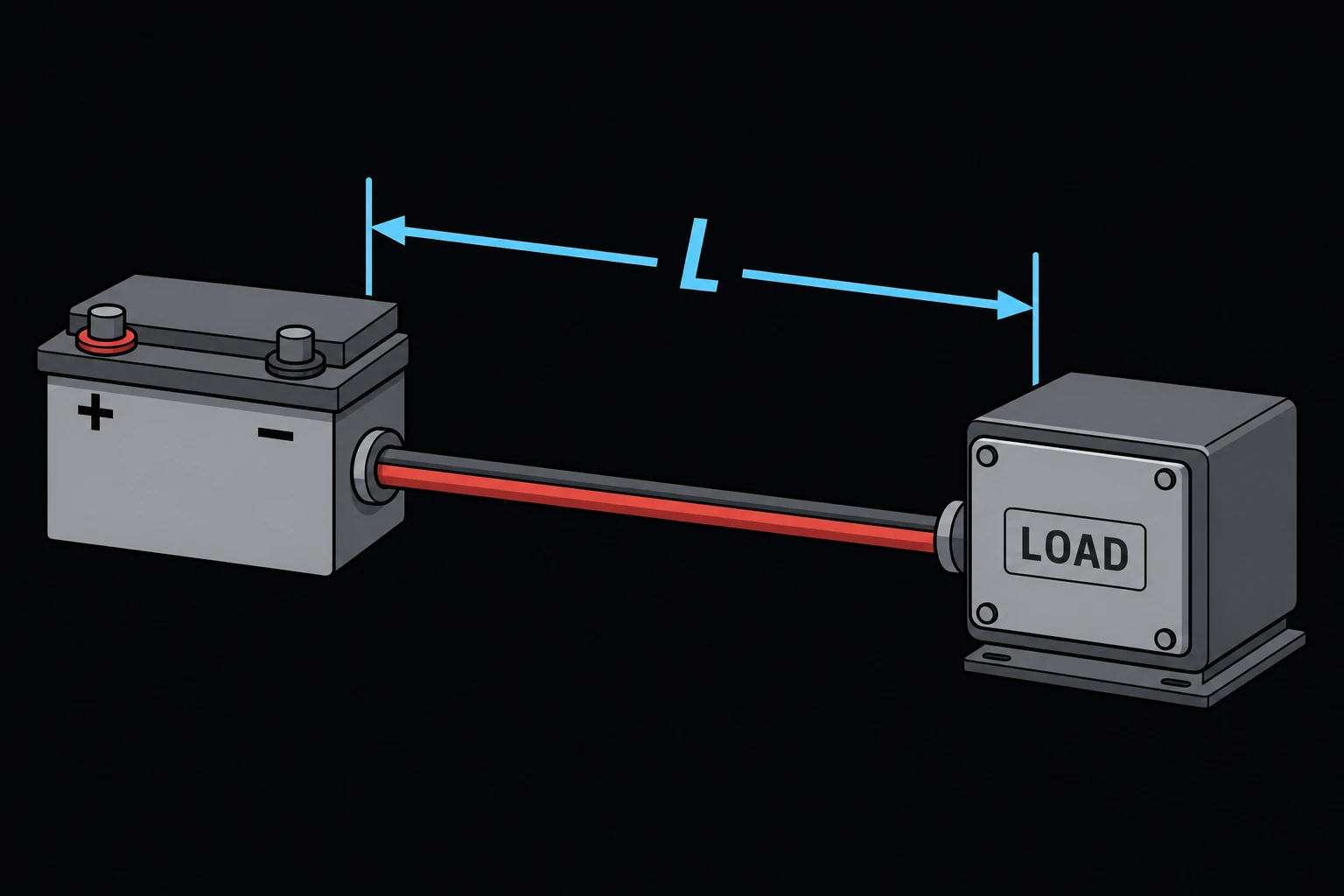
I is the load current in amperes, L the one-way length in feet and A the conductor area in circular mils from NEC Chapter 9 Table 8. K is the resistivity at 75 °C: 12.9 Ω·cmil/ft for copper and 21.2 for aluminum, from the same table [1]. The 2 counts the current going out and coming back. The percentage is Vd divided by the source voltage.
Limits and common mistakes
- The drop formula is for a single-phase or DC circuit. For a balanced three-phase circuit, multiply the drop by 0.866 (√3/2). Reactance, which the page ignores, adds to the drop on large conductors in steel conduit.
- Count only current-carrying conductors. A neutral carrying only the imbalance and the equipment ground don’t count.
- Size for 125 % of a continuous load (3 hours or more). The page uses the current you enter as it is.
Worked example
A 240 V, 40 A load sits 150 ft from its panel. The run uses copper THWN-2 in a conduit with three current-carrying wires, through a space that reaches 35 °C. The breaker and the load have 75 °C terminals. The drop must stay within 3 %.
- Choose Mode Find minimum gauge, Conductor material Copper and Insulation temperature rating 90 °C (e.g. THHN, THWN-2, XHHW-2).
- Enter Load current (I) 40 A, One-way run length (L) 150 ft, Source voltage (V) 240 V and Max allowable voltage drop (%) 3.
- Choose Ambient temperature (NEC Table 310.15(B)(1)(1)) 31–35 °C (87–95 °F), Current-carrying conductors in the raceway or cable 1–3 (× 1) and Terminal temperature rating 75 °C. Press Solve. The Solution shows:
Minimum gauge: 6 AWG
Ampacity (Table 310.16, 90 °C copper): 75 A
Ambient temperature correction factor: 0.96
Adjustment factor for the number of conductors: 1
Allowable ampacity (after factors, limited to the 75 °C column for the terminals): 65 A
Voltage drop: 5.89939 V
Voltage drop (%): 2.45808 %
Check: 75 × 0.96 = 72 A, held to the 65 A of the 75 °C column. 8 AWG would carry the current (50 A) but drops 2 × 12.9 × 40 × 150 / 16,510 = 9.38 V, or 3.9 %. The voltage drop, not the ampacity, sets the size.