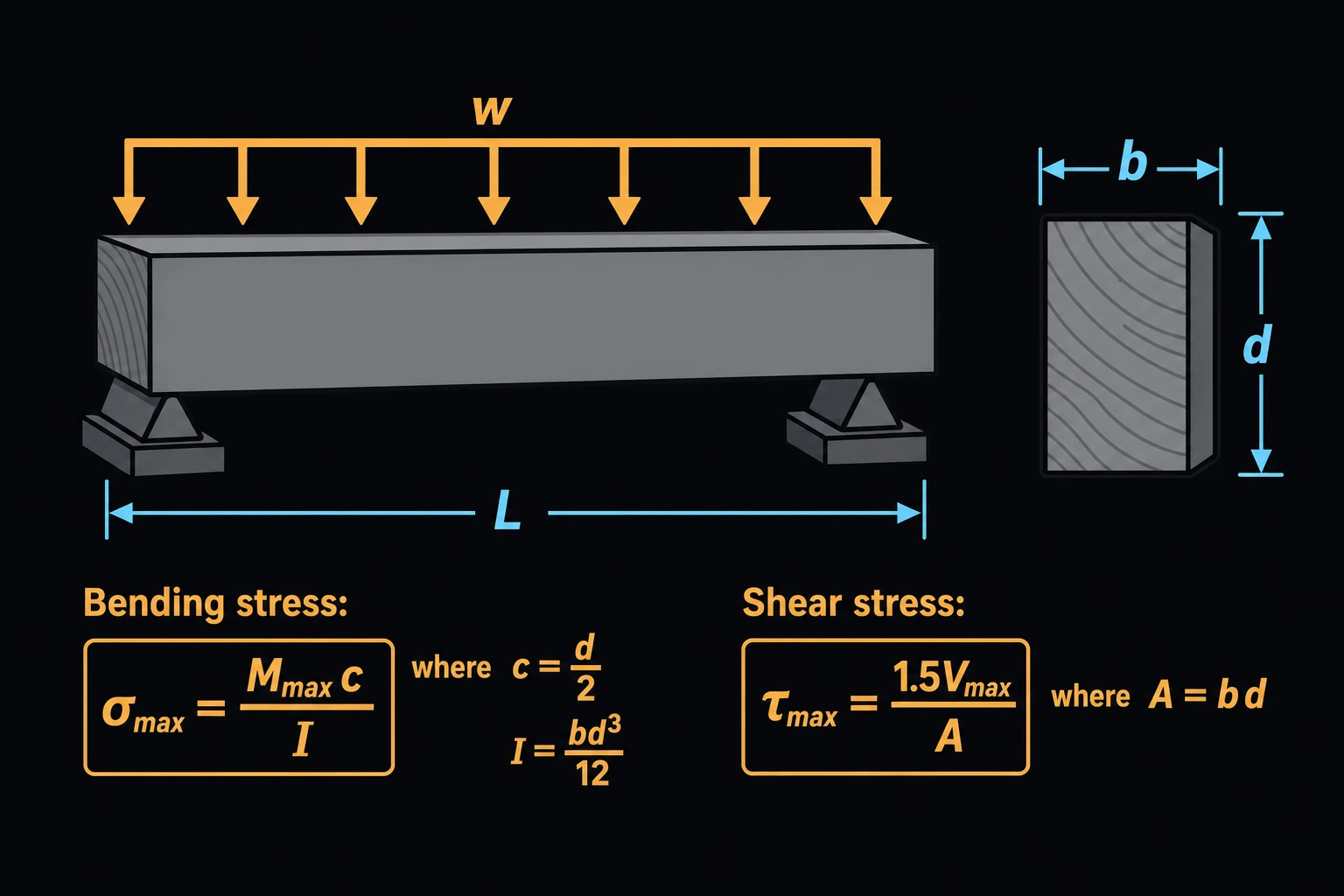
Wood Beam Bending & Shear Check (NDS)
Checks the bending and shear stresses in a rectangular sawn-lumber beam, joist or header against the adjusted design values of the NDS, by allowable stress design (ASD) [1]. Pick a nominal size and a species and grade, and the page starts from the reference values for visually graded dimension lumber in NDS Supplement Table 4A [3] and applies the adjustment factors. Or choose Custom and enter your own section and adjusted values. Designers and plan checkers use it to confirm or size a member.
The equations
fb = M/S, S = bd²/6
fv = 1.5V/(bd)
M is the applied moment and V the applied shear, both from service (ASD) loads. b is the beam’s width and d its depth, the dressed dry dimensions of NDS Supplement Table 1B [3] when you pick a nominal size. S is the section modulus. The 1.5 is the peak shear stress at the neutral axis of a rectangle.
The adjusted design values come from NDS Table 4.3.1 [1]:
Fb′ = Fb·CD·CM·CF·Cr
Fv′ = Fv·CD·CM
CD is the load duration factor: 1.0 for occupancy live load, 1.15 for snow, 1.6 for wind. CM is the wet service factor, applied when the wood stays above 19 % moisture. CF is the size factor for the nominal depth. Cr = 1.15 applies to three or more members at 24 in on center or less that share the load, such as floor joists. The beam passes when both ratios f/F′ are 1 or less. The page also gives E′ for a deflection check.
Limits and common mistakes
- The beam stability factor CL is taken as 1, which needs the compression edge braced, for example by sheathing nailed to the top of the joists. The page also takes the temperature factor Ct and the incising factor Ci as 1 and assumes the load bears on the narrow face.
- Pick the load duration of the shortest load in the combination; dead load alone uses 0.9 [1].
- Table 4A covers dimension lumber 2 to 4 in thick. For timbers, glulam and engineered lumber, use Custom.
- Shear may be taken at a distance d from the support face [1], so the full end shear is conservative.
Worked example
Floor joists of 2×10 Douglas Fir-Larch No. 2 at 16 in on center span 4.0 m. With 2.4 kPa of total load on a 0.406 m strip, each joist carries 0.975 kN/m, so M = wL²/8 = 1.95 kN·m and V = wL/2 = 1.95 kN.
- Enter Applied Moment 1.95 and Applied Shear 1.95.
- Choose Nominal Size 2×10 and Species and Grade Douglas Fir-Larch, No. 2.
- Choose Load Duration Ten years, Service Condition Dry and Repetitive Member Yes.
- Press Solve. The Solution shows:
Bending stress fb: 5.56301 MPa
Bending ratio fb / Fb': 0.708693
Shear stress fv = 1.5V/(bd): 0.326757 MPa
Shear ratio fv / Fv': 0.26329
Result: OK
Adjusted Fb' = Fb·CD·CM·CF·Cr: 7.84968 MPa
Check in US units: S = 1.5 × 9.25² / 6 = 21.39 in³, and 1.95 kN·m is 17,259 lb·in, so fb = 807 psi. Fb′ = 900 × 1.1 × 1.15 = 1,138.5 psi, and 807/1,138.5 = 0.709.